The Symphony of Sensation: Adding Haptic Feedback to Your Keyboard
A detailed guide to adding smartphone-style vibration feedback to your custom keyboard using linear resonant actuators.
February 19, 2025 — Nidhish Shah
Most modern phones give you a subtle buzz with each tap on the screen. This haptic feedback makes typing feel more precise and satisfying — yet it's notably absent from most custom keyboards. While the keyboard community has created countless tutorials on nearly every aspect of switches, finding resources on adding haptic feedback is surprisingly difficult.
This guide covers the full process of adding a haptic system to a custom keyboard. I'll walk through component selection, installation, and writing the ZMK firmware to control the linear resonant actuators (LRAs). Whether you're planning your next build or just curious about what's possible, you'll learn what it takes to add this extra dimension to your typing experience.
Table of Contents
Why add Haptic Feedback?
If you've used a split mechanical keyboard, you're probably familiar with layers and combos. These aren't just convenient features; they're essential for maintaining efficiency with a reduced key count. However, there's a subtle usability cost: they often lack immediate feedback.
Think about it. When you hold a home row mod key or activate a layer, there's no immediate visual indication on your screen. You only discover if the mod or layer activated correctly after you press the next key.
This feedback becomes particularly valuable for:
- Layer activation: Get immediate confirmation when you've switched to your symbols or navigation layer.
- Home row mods: Feel when you've held a key long enough to activate its modifier function.
- Combos: Know exactly when your key combination registered.
- Timing-sensitive keys: Perfect those hold-tap durations with tactile guidance.
The beauty of custom haptics is that you can tune the feedback to your needs. You can set light vibrations for layer changes, stronger ones for combo activations, or different patterns for specific events.
Understanding the Schematics
Heads up!
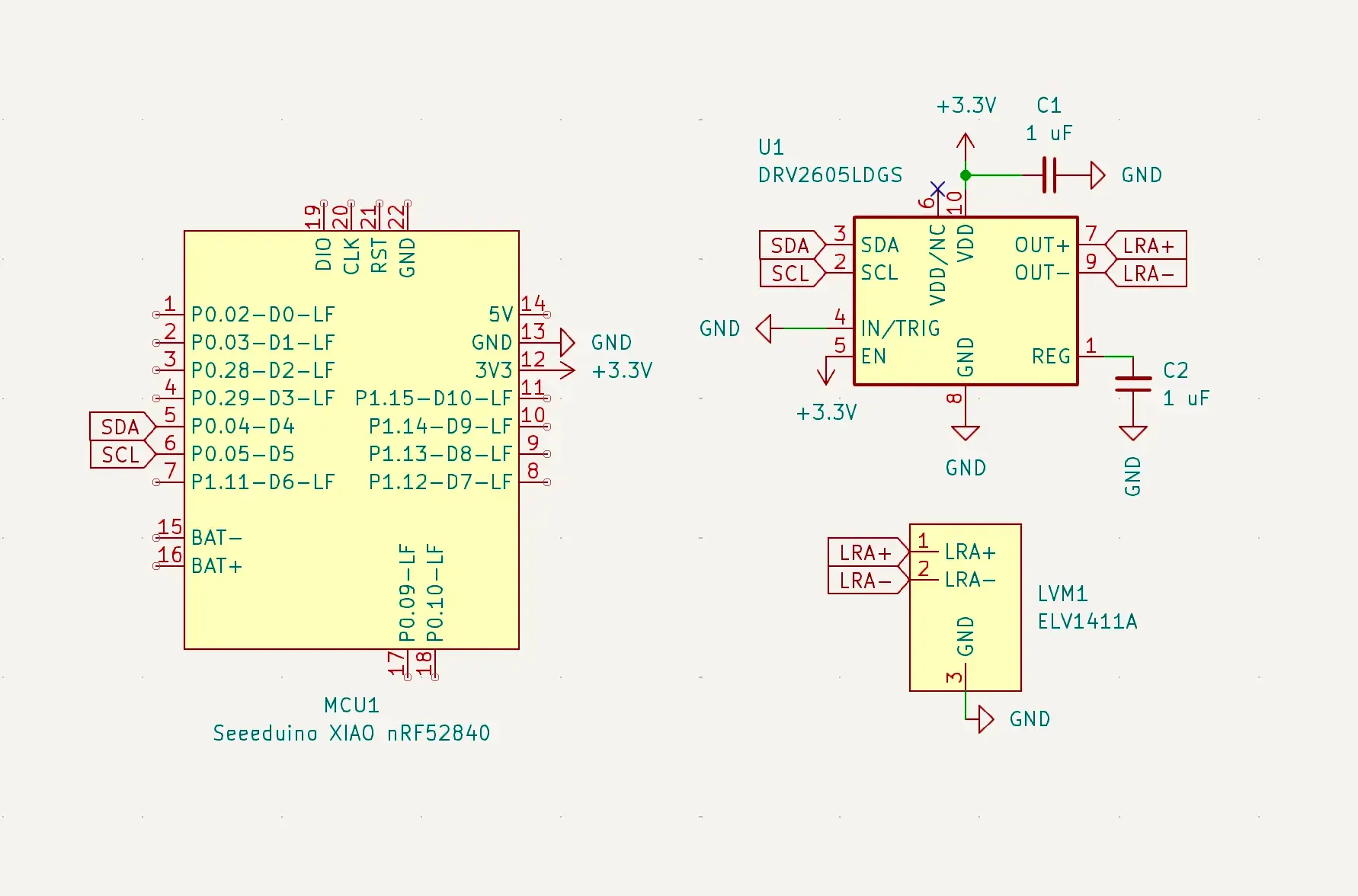
The haptic feedback system consists of three main components:
- MCU: The brain of the operation, handling I2C communication and timing control. Lately I've been enjoying the Seeeduino XIAO nRF52840.
- DRV2605LDGS Driver: A specialized haptic driver IC that generates the precise waveforms needed for the LRA.
- Linear Resonant Actuator: The physical component that creates the vibration. I prefer using the ELV1411A, but other LRAs work just fine.

Component Breakdown
The DRV2605L is connected to the MCU via I2C. For the XIAO, the default SDA and SCL lines are at pin P0.04-D4 and pin P0.05-D5 respectively. The power connections are as follows:
VDD/VNCconnects to +3.3V with a 1µF decoupling capacitor (C1).REGpin has a 1µF capacitor (C2) to ground.IN/TRIGis grounded since we're using I2C mode.ENpin is pulled high to enable the device.
Key Design Considerations:
- We connect the
ENpin to +3.3V instead of a GPIO. Currently, the ZMK Driver for DRV2605L doesn't support theENpin (yet?), so save yourself the extra GPIO 😉. The power draw is also minimal (~2µA). - While the datasheet specifies a 0.1µF capacitor for
VDD, this is a minimum requirement. We can use 1µF capacitors for bothVDDandREGpins to simplify our bill of materials and make hand-soldering easier.
Laying Down the Circuit: PCB Layout Essentials
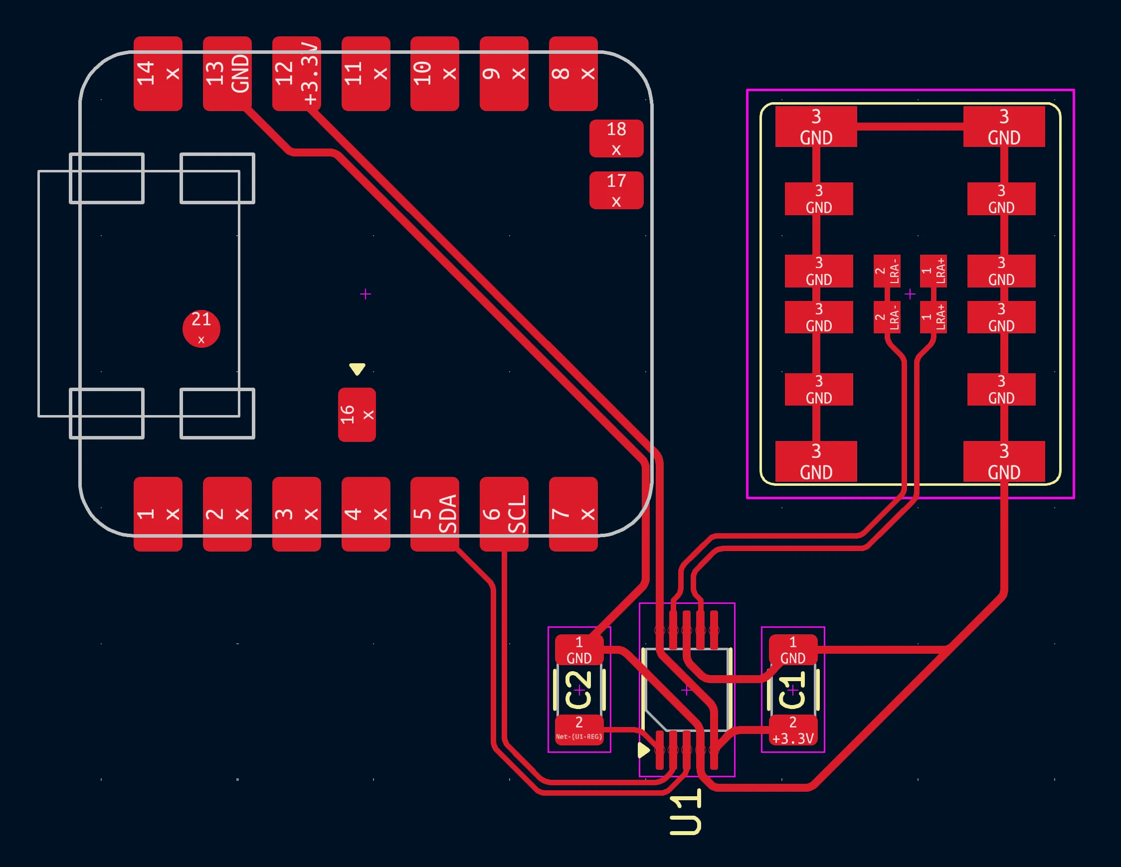
After finalizing our schematic, we need to carefully consider how to arrange these components on our PCB. While the circuit itself is straightforward, a few key layout decisions can make the difference between crisp, reliable haptic feedback and inconsistent performance.
Footprints
- DRV2605LDGS: KiCad's default
VSSOP-10_3x3mm_P0.5mmfootprint works well. If you need reversible PCBs, use this reversible version. - ELV1411A LRA: You can find both standard and reversible footprints in my repository.
- Seeeduino XIAO nRF52840: The XIAO has underside battery pins which require some creativity. Use this reversible version (requires hot-plate) for reversible PCBs, or this through-hole standard version for traditional layouts.
- Capacitors: KiCad's standard
C_1206_3216Metricfootprints work perfectly here, but here's a reversible version.
The reversible footprints are designed for PCBs that use the same design for both left and right halves. For keyboards with dedicated left/right PCBs or single-piece designs, use the standard versions.

Design Tips
- Component Placement
- The DRV2605L's decoupling capacitors must be placed as close as possible to their respective pins (
VDDandREG). - Keep the
LRA+andLRA-traces symmetrical (as much as possible) and avoid crossing them.
- The DRV2605L's decoupling capacitors must be placed as close as possible to their respective pins (
- Power Routing
- If space allows, use wider traces (e.g 0.3mm) for ground and power connections.
- Keep the traces connecting the DRV2605L to its capacitors as short and direct as possible.
- LRA Mounting
- The LRA must have solid mechanical contact with the case/plate to effectively transfer vibrations.
Assembly
Attention!
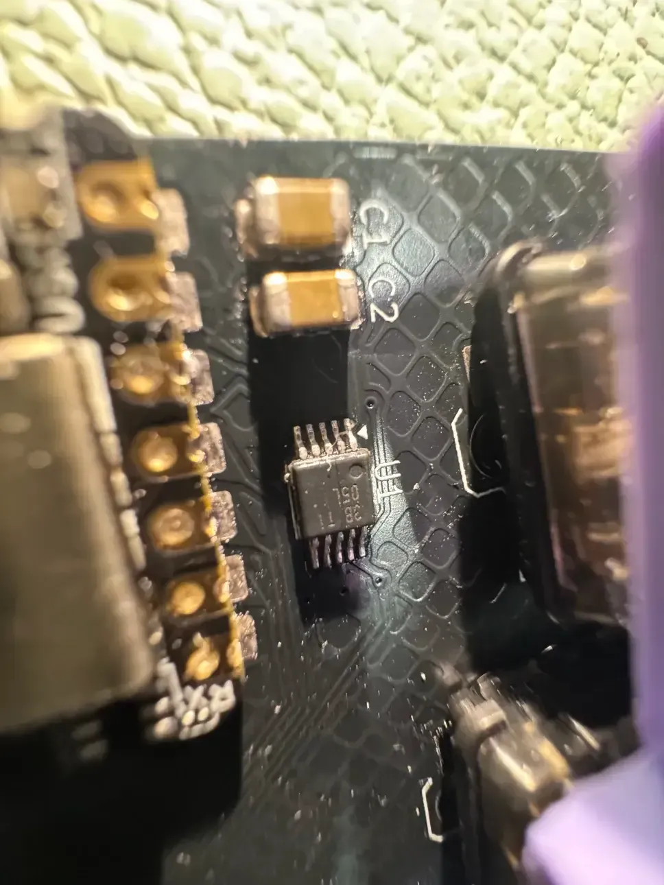
The DRV2605L's tiny VSSOP-10 package makes assembly challenging. Using a stencil and hot plate is strongly recommended, but hand-soldering is possible with generous flux and the drag soldering technique.

The other components (capacitors, LRA, and XIAO) are relatively straightforward to solder. After assembly, use a multimeter to verify there are no shorts between power and ground, and check continuity of the I2C lines.
Tip
The Firmware
Since ZMK mainline doesn't have haptic support yet, we need to use the following three modules.
To add the modules to your ZMK config, update your config/west.yml file.
manifest:
  remotes:
    - name: zmkfirmware
      url-base: https://github.com/zmkfirmware
    - name: badjeff
      url-base: https://github.com/badjeff
  projects:
    - name: zmk
      remote: zmkfirmware
      revision: v0.1
      import: app/west.yml
    - name: zmk-output-behavior-listener
      remote: badjeff
      revision: d6f2f4c
    - name: zmk-split-peripheral-output-relay
      remote: badjeff
      revision: 014b549
    - name: zmk-drv2605-driver
      remote: badjeff
      revision: 81a386a
  self:
    path: config
zmk-split-peripheral-output-relay module is used for communication of output events between the central and peripheral side. For unibody builds, this module is not required.Shield Definition
To set up the DRV2605L driver, we need to configure the SDA and SCL lines. For a pin labeled PX.Y, the configuration format is <NRF_PSEL(TWIM_SDA, X, Y)> for the SDA line and <NRF_PSEL(TWIM_SCL, X, Y)> for the SCL line. In our case, the SDA line is connected to pin P0.04-D4, so we use <NRF_PSEL(TWIM_SDA, 0, 4)>. Similarly, the SCL line is connected to pin P0.05-D5, so we use <NRF_PSEL(TWIM_SCL, 0, 5)>.
Next, we must set up the I2C bus with the DRV2605L driver, specifying it's address. For the XIAO, the &xiao_i2c node label is exposed. Similarly, for Pro-Micro compatible boards, you may use the &pro_micro_i2c node. Check the ZMK documentation for more details.
Thus, the following code snippet can be added to your board.overlay file (for unibody builds), or the board.dtsi file (for split keyboards).
&pinctrl {
    i2c0_default: i2c0_default {
        group1 {
            psels = <NRF_PSEL(TWIM_SDA, 0, 4)>, // define your SDA pin.
                    <NRF_PSEL(TWIM_SCL, 0, 5)>; // define your SCL pin.
        };
    };

    i2c0_sleep: i2c0_sleep {
        group1 {
            psels = <NRF_PSEL(TWIM_SDA, 0, 4)>, // define your SDA pin.
                    <NRF_PSEL(TWIM_SCL, 0, 5)>; // define your SCL pin.
            low-power-enable;
        };
    };
};

&xiao_i2c {
    status = "okay";
    compatible = "nordic,nrf-twim";

    drv2605_0: drv2605@5a {
        compatible = "ti,drv2605";
        reg = <0x5a>;
        library = <6>;  // LRA
        standby-ms = <1000>;
    };
};
Next we define the devices. For unibody builds, add the following snippet to board.overlay:
/ {
    haptic: haptic {
        compatible = "zmk,output-haptic-feedback";
        #binding-cells = <0>;
        driver = "drv2605";
        device = <&drv2605_0>;
    };
};
For split builds, ensure that the zmk-split-peripheral-output-relay module is included in your config/west.yml. Add the following to board-left.overlay (central side):
/{
    haptic_l: haptic_l {
        compatible = "zmk,output-haptic-feedback";
        #binding-cells = <0>;
        driver = "drv2605";
        device = <&drv2605_0>;
    };

    haptic_r: haptic_r {
        compatible = "zmk,output-split-output-relay";
        #binding-cells = <0>;
    };

    output_relay_config_201_l {
        compatible = "zmk,split-peripheral-output-relay";
        device = <&haptic_r>;
        relay-channel = <201>;
    };
};
Similarly, we add the following to board-right.overlay (peripheral side). Here, you must create a dummy node &haptic_l to assist in compiling the firmware:
/{
    // dummy device to make the overlay compile
    haptic_l: haptic_l {
        compatible = "zmk,output-split-output-relay";
        #binding-cells = <0>;
    };

    haptic_r: haptic_r {
        compatible = "zmk,output-haptic-feedback";
        #binding-cells = <0>;
        driver = "drv2605";
        device = <&drv2605_0>;
    };

    output_relay_config_201_l {
        compatible = "zmk,split-peripheral-output-relay";
        device = <&haptic_r>;
        relay-channel = <201>;
    };
};
Keymap Definition
The zmk-output-behavior-listener module has excellent documentation and examples in its README.md file. To simplify our keymaps and minimize repetitive code, I created some macros for a cleaner setup.
#define HAPTIC_OBG(node_name, device_ref, force_val) \
    node_name: node_name {                           \
        compatible = "zmk,output-behavior-generic";  \
        #binding-cells = <0>;                        \
        device = <device_ref>;                       \
        force = <force_val>;                         \
    };

#define OUTPUT_SOURCE_LAYER_STATE_CHANGE 1
#define HAPTIC_LAYER(node_name, bindings_list, layers_list)  \
    node_name: node_name {                                   \
        compatible = "zmk,output-behavior-listener";         \
        bindings = bindings_list;                            \
        layers = layers_list;                                \
        sources = <OUTPUT_SOURCE_LAYER_STATE_CHANGE>;        \
        all-state;                                           \
    };

#define OUTPUT_SOURCE_KEYCODE_STATE_CHANGE 3
#define HAPTIC_KEYCODE(node_name, keycode, bindings_list, layers_list) \
    node_name: node_name {                                             \
        compatible = "zmk,output-behavior-listener";                   \
        bindings = bindings_list;                                      \
        position = keycode;                                            \
        layers = layers_list;                                          \
        sources = <OUTPUT_SOURCE_KEYCODE_STATE_CHANGE>;                \
    };
Here's an example keymap with the macros:
/* Layer Definitions */
#define DEFAULT 0
#define LAYER1  1
#define LAYER2  2

/ {
    // setup output behaviors for both the left, and right haptic devices.
    HAPTIC_OBG(hl_dc_strong_1, &haptic_l, 27)
    HAPTIC_OBG(hr_dc_strong_1, &haptic_r, 27)
    HAPTIC_OBG(hl_strong_click_1, &haptic_l, 1)
    HAPTIC_OBG(hr_strong_click_1, &haptic_r, 1)

    // setup output listeners for keycodes and layers.
    HAPTIC_KEYCODE(haptic_lshift, <0xE1>, <&hl_dc_strong_1>, <DEFAULT>)
    HAPTIC_KEYCODE(haptic_rshift, <0xE5>, <&hr_dc_strong_1>, <DEFAULT>)
    HAPTIC_LAYER(haptic_l1, <&hl_strong_click_1>, <LAYER1>)
    HAPTIC_LAYER(haptic_l2, <&hr_strong_click_1>, <LAYER2>)
};
Note that the force parameter in the output behavior definition corresponds to the waveform effect from the DRV2605L library. For a complete list of effects, refer to section 11.2 of the DRV2605L datasheet. Additionally, the keycode values align with the usage IDs found in the HID Usages document.
Conclusion
So... we are at the end of the journey! Adding haptic feedback to your custom keyboard is a rewarding project. By following this guide, you've learned how to select the right components, design and assemble the PCB, and configure the firmware to bring your keyboard to life with tactile feedback.
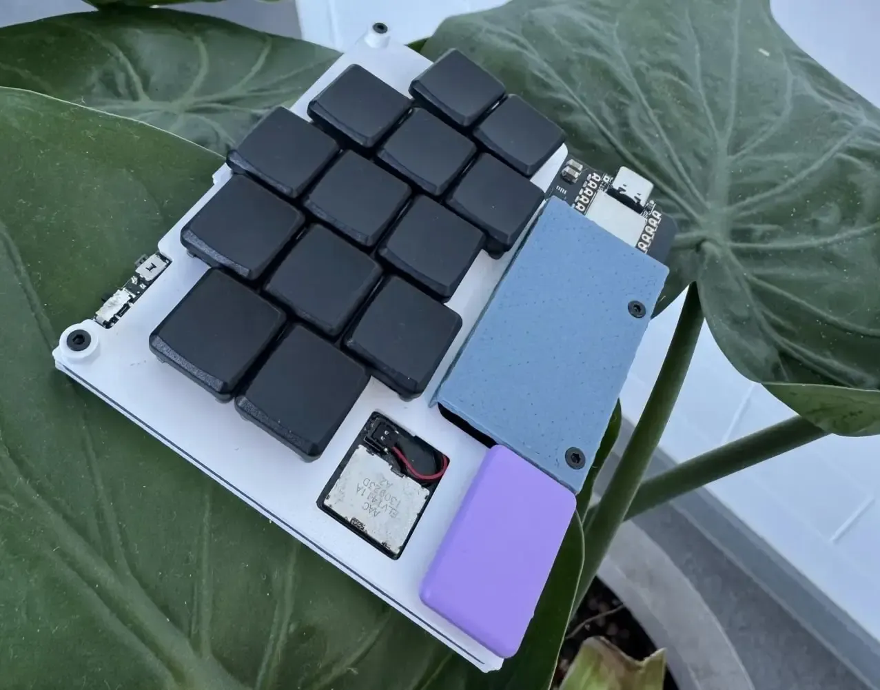
As you continue to explore and experiment with your keyboard builds, remember that the possibilities for personalization are endless. Thank you for joining me on this journey. I hope you found this guide helpful and inspiring. Happy building, and may your keyboard be as expressive as your creativity allows! Here's a keyboard I designed to prototype haptic feedback 😄.
